Design
Mechanical Design
One of the most difficult parts of this project was getting the knobs of the Etch-A-Sketch to move. We had to choose between either a stepper, continuous servo, regular servo, or regular DC motor. Since we weren't going to implement a camera to track the movement of the sketcher's cursor, we wanted a motor that could give reliable open loop control, therefore we chose a stepper motor. Originally, we used old stepper motors like this.
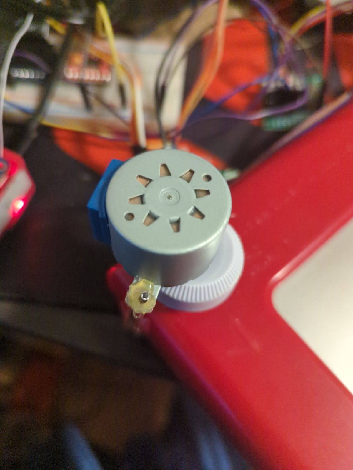
Figure 2: Previous stepper motors
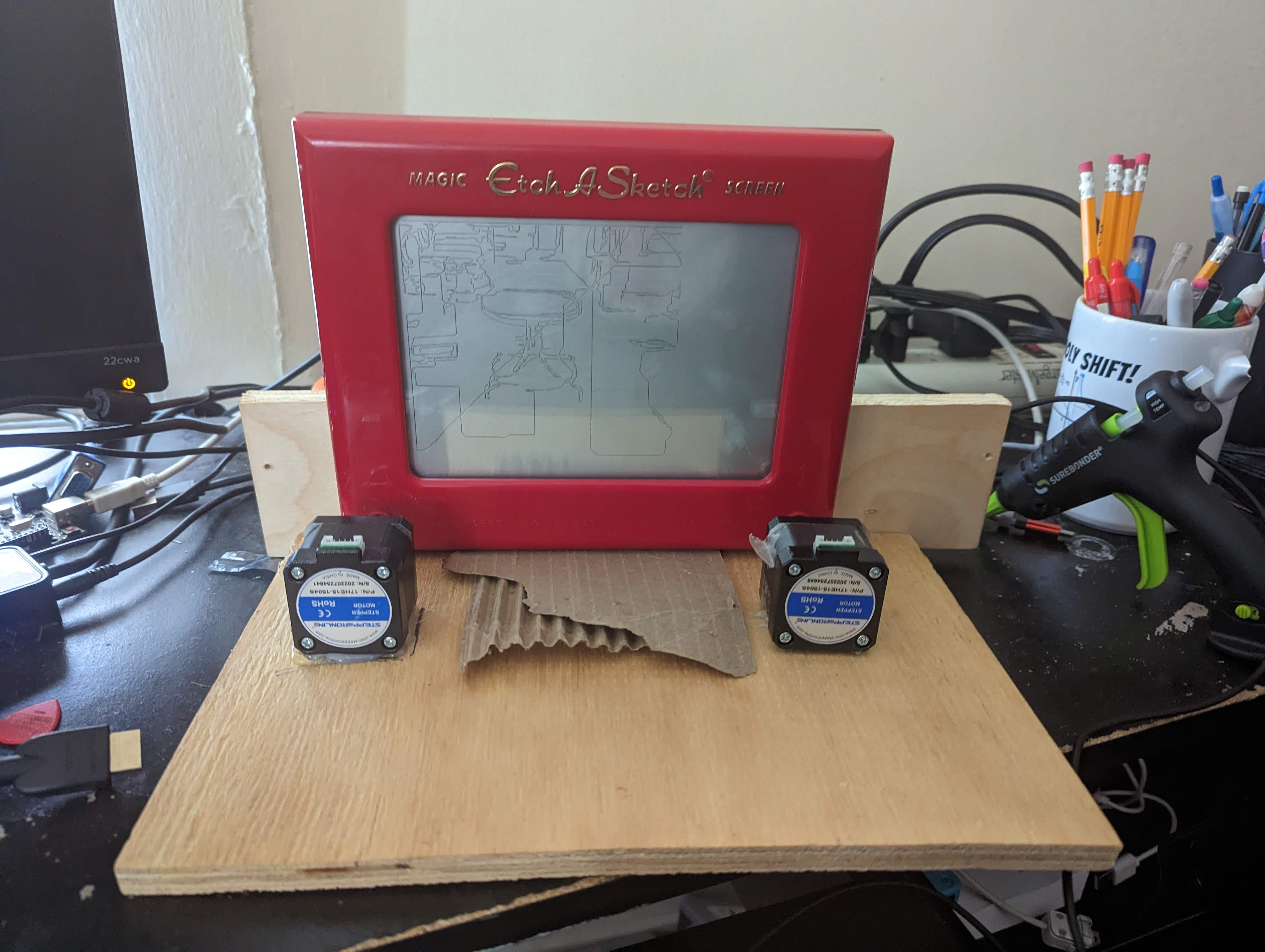
But unfortunately these motors did not have enough torque to consistently move the knobs of the etch-a-sketch. source (5) and (4) showed the difference in effectiveness of larger stepper motors. The motors would get stuck often and would struggle on drawing small lines on the etch-a-sketch. Instead, we opted for NEMA17 motors with stall torque of 42N/cm. This was plenty of torque to control the etch-a-sketch knobs easily.
In order to get the motors attached to the etch-a-sketch knobs, we had to create type of axle coupler mechanism. To do this, we used heat shrink and shrunk onto both the motor axle as well as the etch-a-sketch knob stem as discussed by source (4). By doing this, we created a tight seal between the two rods. Though the connection allowed synchronous rotation between the etch-a-sketch and the motors, the physical connection was flexible and prone to tearing, so we created a wooden platform for the etch-a-sketch and the motors Shown in figure 1.
With this done, we finally had a working mechanism to control the etch-a-sketch. The next task was interfacing the motors with the raspberry pi.
Circuit Design
In terms of circuitry, we simply needed to control 2 stepper motors. To do this we used two A4998 drivers. These drivers have a pinout according to this diagram
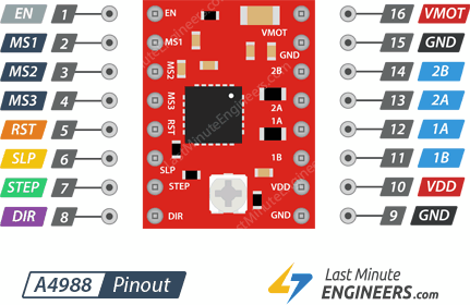
Figure 3: Motor driver pinout (1)
The important pins were the ground, VMot (Supply voltage), and VDD (logic voltage), so VMot would be connected to a power supply, VDD to the 3.3V pin on the raspberry pi, and the ground pins would be connected.
The pulse pins and direction pins were connected to gpio pins as the pulse pin make the motors step at each rising edge of the pulse pin and the direction pin must hold the logic level of the current direction of spin. We also connected the sleep pin to a gpio pin as in order to eliminate overheating of the driver, we set the sleep pin low before and after executing commands. The MSX pins control the stepping mode of the drivers, but through testing, the stepping mode had no effect on the etch-a-sketch accuracy. The final pins were the connections to the motor itself which we wire according to this pinout.
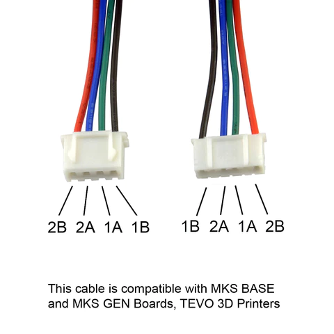
Figure 4: Stepper motor pinout (2)
Here is the final circuit layout.
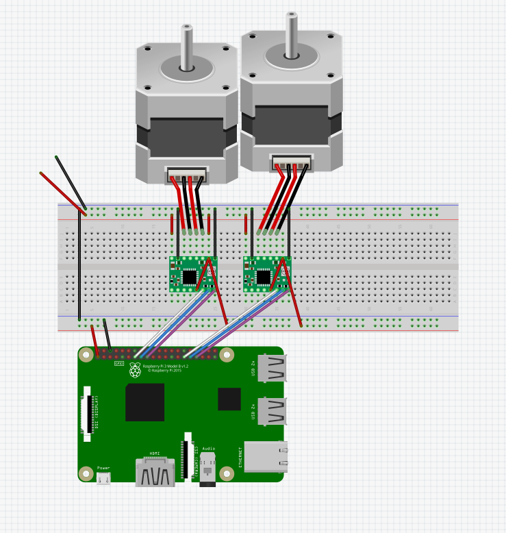
Figure 5: Breadboard layout
In this layout, the gpio numbers are arbitrary since the model is a rasbperry pi 3. In the real device, we used gpio numbers 4,5,6,12,16, and 19 as these pins were available even with the piTFT attached. Also, the reset pin was pulled high as it was active low according to source (1).
In order to have a more consistent and more reliable circuit, we soldered the drivers onto a protoboard with wires attached to the inputs and outputs shown here.
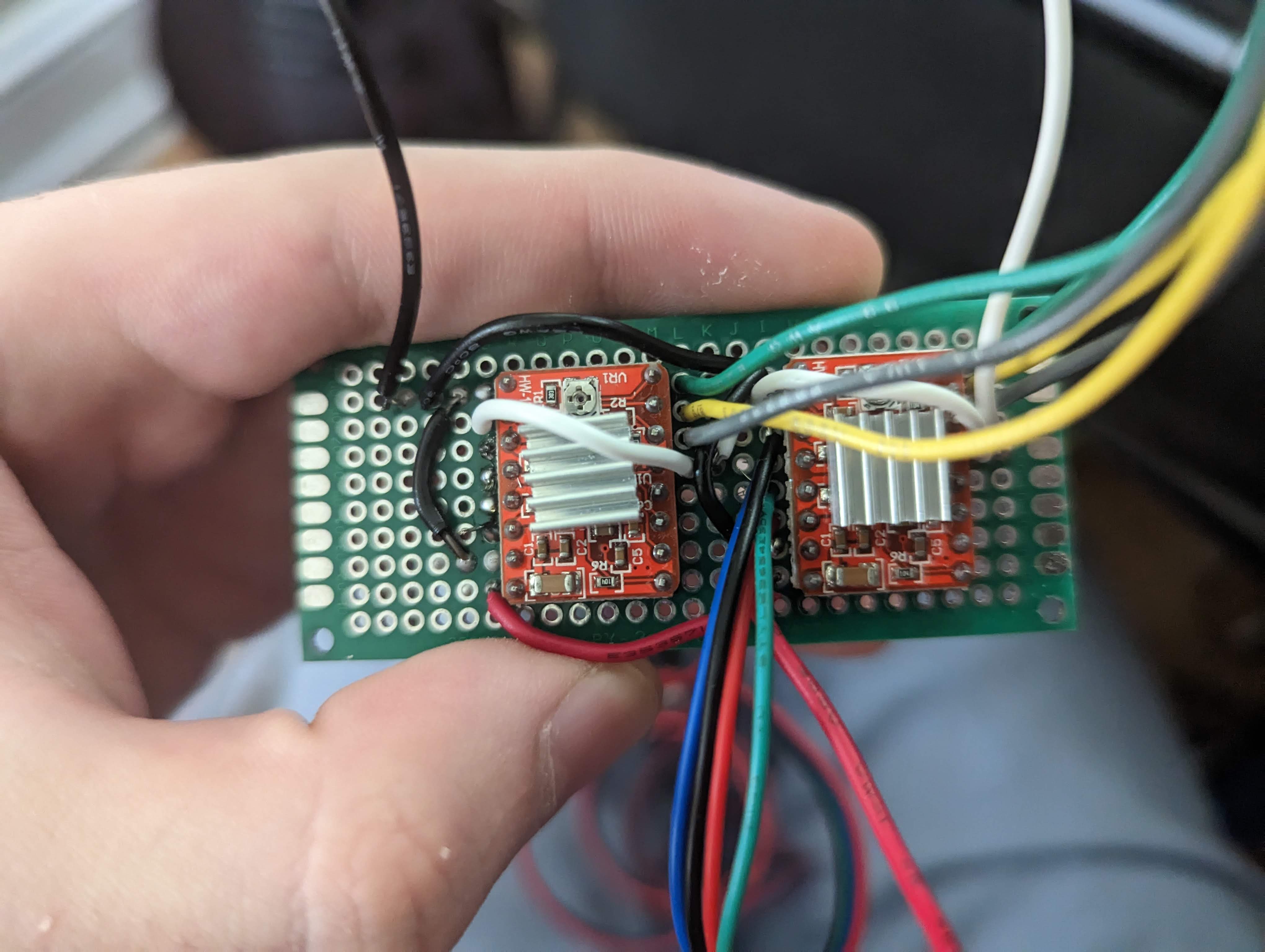
Figure 6: circuit protoboard
PreProcessing
To use a path algorithm to move through an image, we had to convert the image to a sketch-like drawing first. We did this according to source (3). This source explained how to use opencv to convert an image to a sketch-like image. The steps were, invert, blur, invert the blurred image, divide the inverted image by the inverted blurred image. These steps produced a sketch-like-image from any given image. Here is an example of the pre-processing script
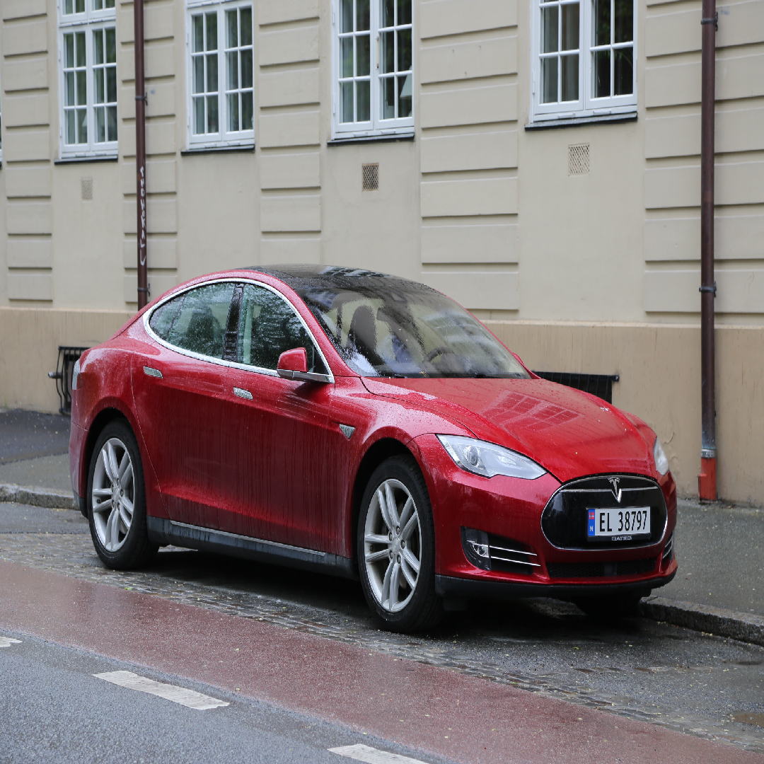
Figure 7: Image before pre-processing
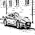
Figure 8: Image after pre-processing
Path Algorithm
The path algorithm converted an image into a trace of the image. The processed image was converted into a 2D grid of binary points: points that were filled in and points that were not. The algorithm was a modification to Djisktra's shortest path algorithm, with frontier a node adding adjacent nodes to a frontier set, then travelling to the next frontier node. The algorithm worked like this, with every movement from a node to a node being recorded in a list.
- Travel filled-in nodes in a line until reaching a blank spot. Add adjacent nodes to frontier set.
- Find the lowest cost path to the next frontier node and go there. Cost is orders of magnitude higher if travelling through whitespace.
- Repeat 1 and 2 until you run out of nodes (or, explored a "cluster" of filled in nodes)
- Find the closest un-filled-in node (radiate out the image until finding one). If there are none, finish.
- Add that node to the frontier set and do #2. Every pixel is added to a path list whenever it's travelled/backtracked to , and after every pixel is explored (filled in), turn the list of pixels into movements. To do this, consecutive movements in the same direction were combined. The result of this is a path through all the pixels of the image. The algorithm as described is computationally expensive, requiring potentially thousands iterations of Djikstra's algorithm through thousands of pixels (for our 320x240 images). This was mitigated by limiting the number of nodes considered while performing the shortest path algorithm, working within a speficied "precision factor" that sets a maximum number of nodes considered when travelling to the next frontier node (which we called "backtracking" if it went through already explored nodes). Another pre-processing step we added to simplify the path algorithm was downscaling the image. By doing this, there would be less pixels to process. Despite this simplification, the algorithm takes about 3 minutes to compute on complex, 320x240 images.
Interfacing With Motors
To interface with the motors on the pi, we first made a stepper motor class. This class contained the functions to move a given motor clockwise or counterclockwise for a given amount of steps and at a certain speed.
To do this, a loop for the number of iterations as steps would execute where the pulse pin would be pulsed for the time 1/speed. The direction pin would also be set according to the desired direction. Originally, the sleep pin would be set and unset before each motor step in order to avoid overheating, but the sleep pin needs a 1ms delay for executing a step. To avoid this delay, sleep and wakeup functions were created. On the creation of the motor object, the sleep pin is set and on deletion of the motor object, the sleep pin is unset thus only using the motor during the execution of a program thus lowering efficiency but stopping the 1ms delay.
The constants TYPICAL_SPEED and TYPICAL_STEPS were created to define the motor objects as if a configuration was changed, then the number of steps every motor command made would all be scaled by the same value.
Next, the sketch_motors class was created to interface both motors controlling the knobs at the same time. This had a move command that given a (x,y) vector, would move the etch-a-sketch cursor in that direction. To do this, the motor would scale each motors by the ratio of the y component to the x component. Then, if each component was positive or negative, the motors would be moved clockwise or counterclockwise.
In testing the sketch_motors object, the object had trouble with diagonals. Rather than make a smooth diagonal, the cursor would make a stepping pattern. This was most likely because the way the commands worked, motor_1 would step once and then motor_2 would step. A crude fix to this was to simply make the motor commands two threads that would operate in parallel. In this way, the motors would not wait for eachother and would simply step at their own speed thus fixing the diagonal problem. With this interface created, the commands from the path algorithm could correctly control the motors.
Simulator
The simulator was written in PyGame and was implemented with both an auto mode and a manual mode. The manual mode would take either keyboard, GPIO, or PiTFT touch inputs and use those to control the cursor movement for the drawing. The manual mode was quite simple as it just polled for inputs and when any inputs were recieved, it would run the corresponding function. The auto mode, on the other hand, worked by creating a list of function calls. This was done either by parsing a premade file from the path algorithm, or by running the path algorithm on a new image and grabbing the new resulting file. Once the file was parsed, the simulator would convert each path algorithm movement into a corresponding function and add these functions to a list. The simulator would then run through the list, drawing with a retained cursor position, to emulate an etch-a-sketch. This system was purposely made to be quite easily converted to work on the actual etch-a-sketch motors. The functions were simply instructions of drawing in a certain direction, so when running the sim code for the actual etch-a-sketch, all one had to do was write new functions for how to draw in each direction but with the stepper motors. The functions were also similar to stepper motors in the sim in that they were distance based rather than time based, so these distances could easily be converted to steps for the stepper motor.
UI
To tie everything together, a UI was created that used the PiTFT to select a file, run the path algorithm, see a preview (using the simulator) of the path file, then draw the image on the Etch-A-Sketch. The start page contains options to terminate the menu, pull from git (update), enter the manual control menu, and to select a file to draw. The update button wasn't working due to authentication issues, but this button would have only been used in development.
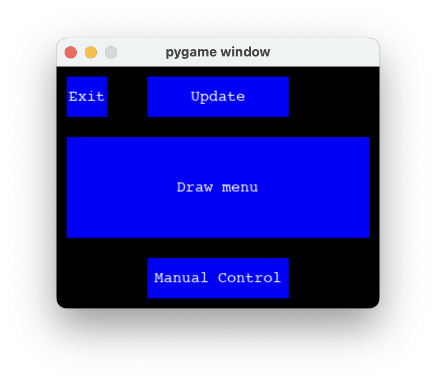
Figure 9: The starting screen of the menu. The Pi booted to this menu. The manual controls drove the motors along one of eight directions, and were used to reset the cursor after drawing an image, due to lack of any position feedback on the stepper motors.
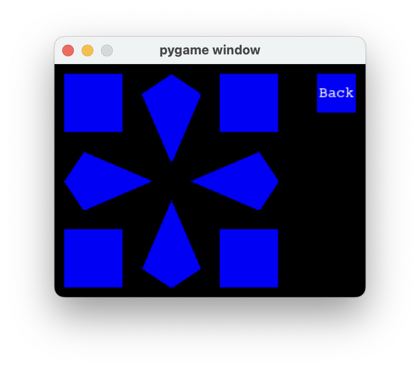
Figure 10: The manual controls menu. There are 8 directions, one for each combination of directions the pair of motors could be operated at.
The file select moved through the images folder on the folder. The image was displayed in the 4:3 aspect ratio it will be traced and drawn in.
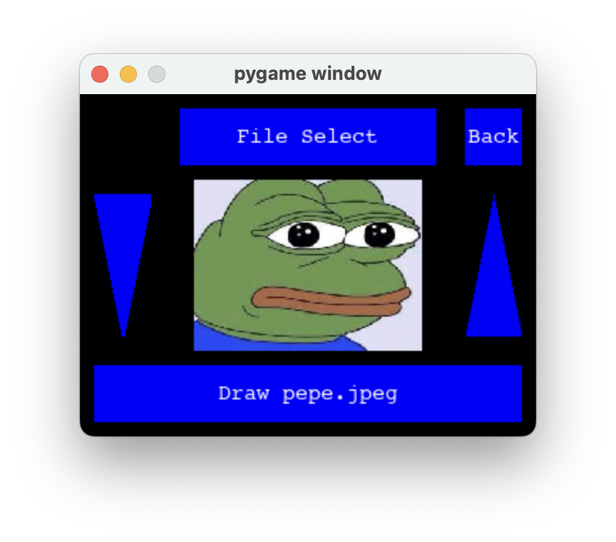
Figure 11: The file select menu. The user can pick an image they would like to draw.
After selecting an image, the path will then be generated for that image.
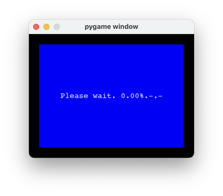
Figure 12: Loading screen ran while the path algorithm was executed. The percentage updated as the path algorithm filled in more nodes.
Once the path is calculated, or if the path had previously been calculated and cached, the image preview screen comes on the screen and options to decrease/increase contrast (the arrows. changing contrast will require the path algorithm to run again and another loading screen comes on) and draw. When the user selects "draw", the image is drawn out using the motors.
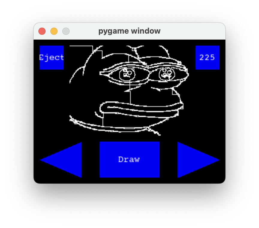
Figure 13: Draw menu. Users can draw the image that will draw like the simulation shown, or adjust contrast.
The menu was implementing threading, with a new thread coming live whenever a button is pressed. A "button" object held information for a function to perform, and this function was ran on a seperate thread. This way the menu could stay responsive even if something was running in the background.
Testing
We were testing constantly at each step. This allowed us to work seperately and integrate the individual pieces of the project with confidence. Since the Simulator, Path Algorithm, and Image Processing were all tested and implemented independently and concurrently, once all 3 parts were done, we were able to combine the different parts together relatively hassle free. Of course, once these software portions were done, we heavily tested them with different images and settings until we were confident that they would translate well to the real world.
The hardware portion was similar, we tested the motors, the frame, and motor controls heavily before combining into the final project. We also built benchmarks of simple shapes to test the accuracy of the motor controls. The closer the cursor was to the original position at the end of a benchmark, the more accurate our motor controls were. Once we had tested the functionality and our motors were sufficiently accurate, we moved on to further implementation and testing of the UI.
Results
In the end, the etch-a-sketch worked as expected for low detail images. Cartoonish images with large curves like the pepe image worked extremely well. Other images with higher detail did much worse as the etch-a-sketch itself could not move in small enough movements to draw fine details appropriately.
The algorithm to process the images worked very well. Any image could be turned into a drawing with enough detail to see the original image in the converted image. On low color contrast images, the algorithm suffered from the unclear lines, but otherwise performed very well.
The goals of the assignment were met as any image could be turned into drawing on the etch-a-sketch. Though the detailed suffered, the original image could be seen in the drawing, therefore our goal for the project was met.
Here are examples of resulting images
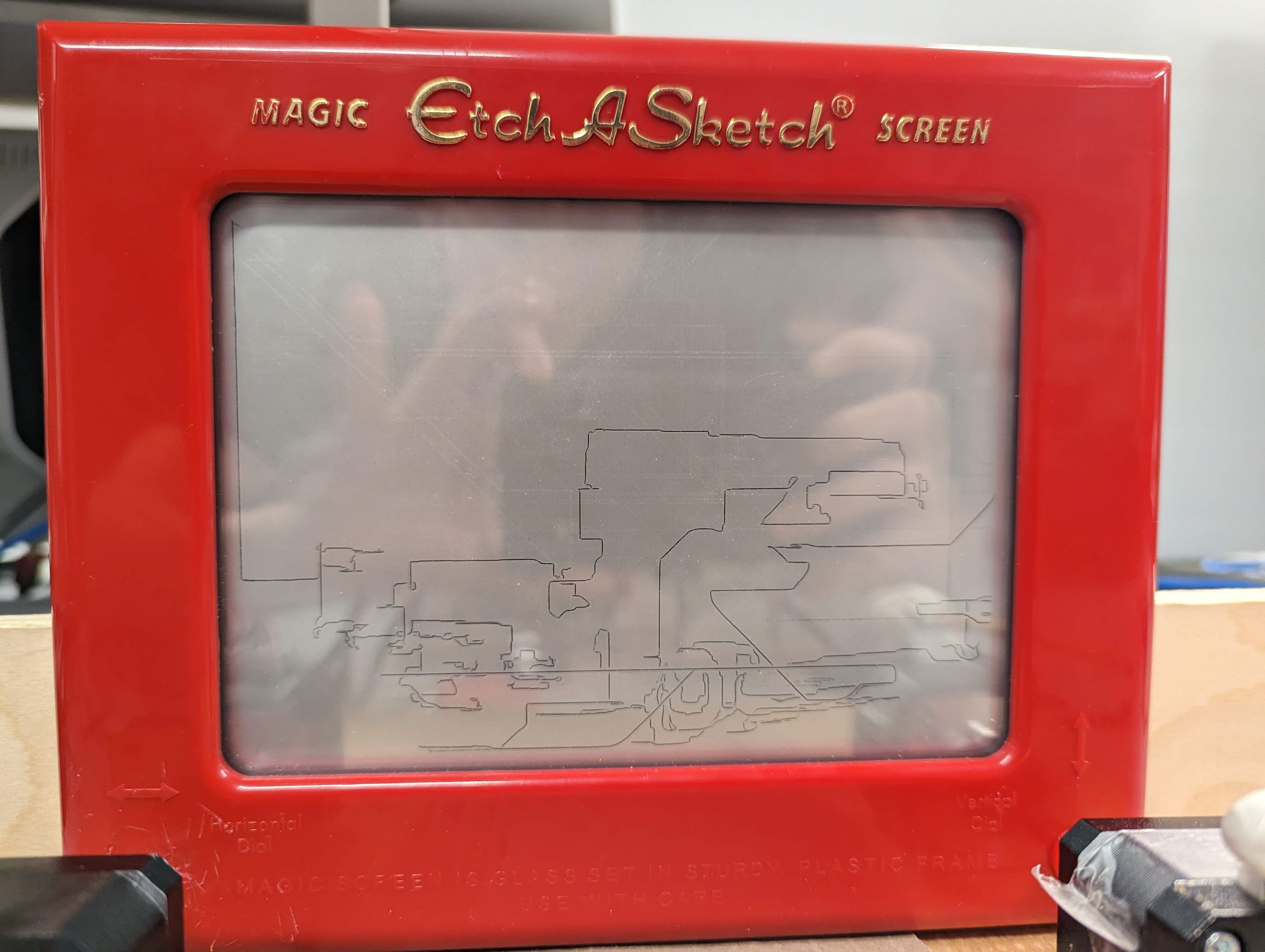
Figure 14: Car on etch-a-sketch
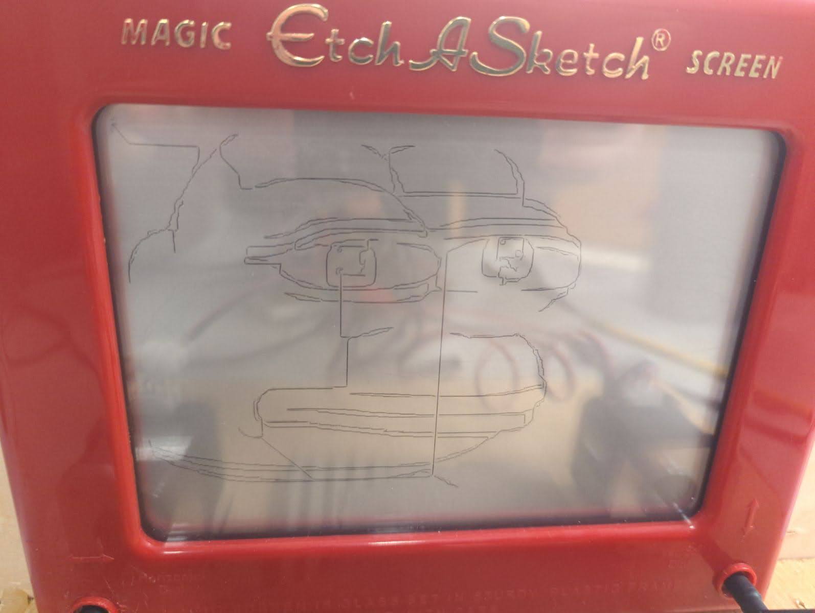
Figure 15: Picture of pepe on etch-a-sketch
Conclusions
This project was a great combination of many import elements in any embedded system: an intuitive, user-friendly, a responsive interface taking full advantage of multiprocessing and threading, and a reliable, robust mechanism behind it. There was some polish left out. For example, multiprocessing could have potentially sped up the shortest path algorithm. The motors, were more robust and precise than expected, but the internals of the Etch-A-Sketch itself were a limiting factor in the precision of the images that could be drawn. The internal device uses an internal pulley that may not have a linear response to the motor speed. This problem could potentially eliminated by using camera feedback, but that's beyond the scope of this project.
Future work
In the future, we may plan to optimize the path planning algorithm for higher precision paths while taking a lower amount of time to process. In source (5), Hunter Adams talked about the slack of the etch-a-sketch pulley system, so somehow accounting for that slack and eliminating it would greatly improve the detail of the output.
Budget
- Personal Budget - 50$
- Raspberry Pi - Borrowed from lab
- PiTFT - Borrowed from lab
- Wood planks (2x) - Found lying around in lab
- Protoboard - from personal collection
- Nema 17 Motor (2x) - 15$
- A4988 Stepper Driver (2x) - 5$
- Etch-A-Sketch - 17$
- Total Cost - 38$
References
https://lastminuteengineers.com/a4988-stepper-motor-driver-arduino-tutorial/ (1)
https://gulfcoast-robotics.com/pages/stepper-cable-for-mks-boards-pinout (2)
https://towardsdatascience.com/generate-pencil-sketch-from-photo-in-python-7c56802d8acb (3)
https://people.ece.cornell.edu/land/courses/ece4760/FinalProjects/s2009/kk383_sl486/kk383_sl486/index.html (4) - Previous year etch-a-sketch project
https://vanhunteradams.com/ (5) - Hunter Adams' etch-a-sketch drawing project
Team member contributions
Liam:
- Integrating stepper motors with etch-a-sketch and raspberry pi
- Pre-processing of images
Ignacio:
- Path-finding algorithm
- Menu UI
Omar:
- path-command simulator
- Mechanical prototyping